How the shell4 element passes its benchmark.
A shell carries load by its curved shape. It is hard to make a finite element that reproduces this. There is a standard set of benchmarks that break simple shell elements. We built a flat-facet shell for physicsbase. We fell into the common trap that makes it about 45% too soft. We corrected it with one term. Then it passed the Scordelis-Lo roof and landed on the reference.
A shell is a plate with curvature, and that curvature changes everything. A flat plate under load resists by bending only. Give it the curve of a roof. Then membrane action carries most of the load. This is in-plane stretching and shearing. Bending has a smaller role. The curvature couples the two mechanisms. It is hard to reproduce this coupling in a computer. Thus the field has a shared set of hard tests. They expose elements that are wrong. The most famous test is the Scordelis-Lo roof. It is the benchmark for every new shell element.
We wanted physicsbase to do shells, and we wanted a simple way. The engine already has a numerically verified in-plane element (quad4, membrane) and plate-bending element (plate4, Reissner-Mindlin). The simple method is to add them together.
A shell from parts you already have
A flat-facet shell approximates a curved surface with many flat quadrilateral facets. It is like a low-poly model of the roof. On each facet, the membrane and the bending are separate, because the facet is flat. Thus the element stiffness is the sum of the two:
\[ \mathbf{K}_{\text{shell}} \;=\; \underbrace{\mathbf{K}_{\text{membrane}}}_{u,\,v\ \text{(quad4)}} \;\oplus\; \underbrace{\mathbf{K}_{\text{bending}}}_{w,\,\theta_x,\,\theta_y\ \text{(plate4)}} \]
Each node has six degrees of freedom: three translations and three rotations. This is the same layout as our 3D frame element. Thus a shell mesh and a frame mesh use one model. The only real work is orientation. Each facet builds a local frame from its own geometry. It computes the stiffness there. Then it rotates the stiffness into global coordinates. On a flat plate this is exact. It reproduces our standalone plate4 results to fifteen digits. This part is easy.
The trap: the sixth degree of freedom
Then we ran the roof. The answer was about 45% too flexible. It got worse as we made the mesh finer. This is the clear sign of a spurious mechanism. The cause is the sixth DOF at each node: the drilling rotation, the twist about the normal of the facet.
The membrane action and the bending give no resistance to that twist. A flat facet has zero stiffness for its drilling DOF. On a single flat plate this is harmless, because you constrain it. But on a curved shell the facets meet at an angle. There, the in-plane (drilling) rotation of one facet is the out-of-plane (bending) rotation of the next facet. With no drilling stiffness, the fold between two facets acts like a hinge. A finer mesh makes each facet flatter and each fold weaker. Thus the structure gets softer with no limit. This is the diverging error.
\[ k_{\text{drill}} \;=\; 10^{-3}\,\cdot\,\tfrac{1}{8}\,\mathrm{tr}(\mathbf{K}_{\text{membrane}}) \]
The coefficient is not special. A sweep shows that the answer is flat across two orders of magnitude near \(10^{-3}\). Too small, and the hinge returns. Too large, and the element locks. At \(10^{-3}\) the roof deflection stops depending on the mesh. It lands on the benchmark.
The benchmark: the Scordelis-Lo roof
The roof (Scordelis and Lo, 1969; made a standard test by MacNeal and Harder, 1985) is a cylindrical shell. Its radius is 25, its length is 50, its angle is 80°, and its thickness is 0.25. Rigid diaphragms support its two curved ends. It sags under its own weight. Its two straight edges are free, and they droop. The benchmark quantity is the vertical deflection at the midpoint of a free edge. The reference value is 0.3024. It is a hard test, because the response is membrane-dominated. Thus an element that is even a little wrong about in-plane behaviour misses by a lot.
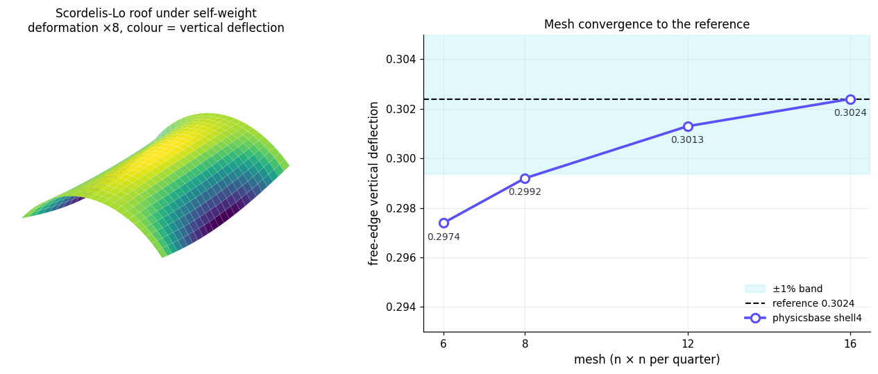
shell4 free-edge deflection reaches the ±1% band around the MacNeal-Harder reference. It stays there as the mesh gets finer.With the drilling term in place, the mesh convergence is clean:
| Mesh | Free-edge deflection | vs 0.3024 |
|---|---|---|
| 6 × 6 | 0.2974 | −1.7% |
| 8 × 8 | 0.2992 | −1.1% |
| 12 × 12 | 0.3013 | −0.4% |
| 16 × 16 | 0.3024 | 0.0% |
The deflection rises steadily toward the reference and lands on it. From an 8×8 mesh the answer is inside the ±1% band. A 16×16 quarter-model gives 0.3024 to four figures. This is a facet shell that passes the benchmark. For contrast, the same meshes without the drilling term give 0.43–0.45. They get worse as the mesh gets finer, about 45% too soft. The difference between a working shell element and a set of hinges is that one stiffness term.
Calling it
To an agent, the shell is another element type. Mesh the surface as flat quads. physicsbase can generate the grid. Assign shell4. Then solve:
POST /v1/solve
{ "nodes": [ /* [x,y,z] on the shell surface */ ],
  "materials": {"s":{"E":4.32e8,"nu":0.0}},
  "elements": [{"type":"shell4","nodes":[…],"material":"s","section":{"t":0.25}}, …],
  "supports": [ /* diaphragm: ux=uy=0 at the ends */ ],
  "loads": [ /* tributary self-weight, -y */ ] }
← displacements, reactions, membrane & bending stresses, verification
Honest footnotes
This is a flat-facet shell. It approximates curvature by facets. The drilling stiffness is an engineering stabilisation, not a variationally-derived drilling field (Allman/Hughes-Brezzi). It reproduces the Scordelis-Lo displacement within the benchmark envelope and can represent folded plates, boxes, and moderately curved shells. Very thin, strongly curved, or shear-sensitive shells require formulation-specific qualification. We used membrane and plate elements already checked by numerical verification. The shell is their sum, plus the drilling term and a 3D transform. This published benchmark is solution-verification evidence, not experimental validation.
References
- R. H. MacNeal & R. L. Harder, "A proposed standard set of problems to test finite element accuracy," Finite Elements in Analysis and Design 1 (1985) 3–20.
- A. C. Scordelis & K. S. Lo, "Computer analysis of cylindrical shells," ACI Journal 61 (1969) 539–561.
- E. N. Dvorkin & K. J. Bathe, "A continuum mechanics based four-node shell element for general non-linear analysis," Engineering Computations 1 (1984) 77–88.
- T. J. R. Hughes & F. Brezzi, "On drilling degrees of freedom," Comput. Methods Appl. Mech. Engrg. 72 (1989) 105–121.
shell4 and solve. The full roof study is a handful of API calls. Read the docs →